

Commercial Touchless Faucet Lifecycle, Maintenance & Commissioning Guide
A commercial touchless faucet should be specified as a maintainable building asset—not treated as a disposable restroom accessory. This guide follows the complete operating lifecycle: application analysis, specification, coordination, installation, commissioning, preventive maintenance, troubleshooting, asset documentation, renewal, and upgrade.
It is written for architects, plumbing and MEP engineers, contractors, commissioning teams, facility managers, building owners, procurement teams, healthcare planners, hospitality operators, universities, airports, stadiums, transit facilities, and other high-traffic commercial environments.
Why Lifecycle Engineering Matters
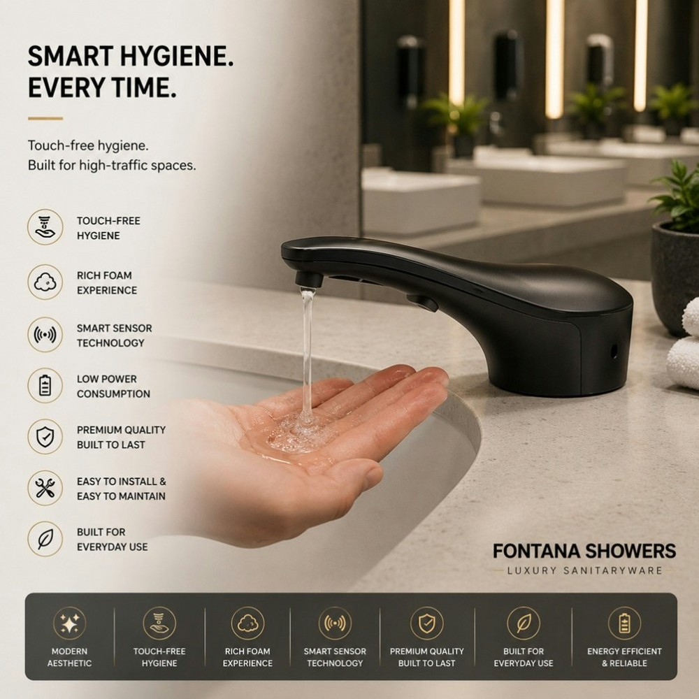
Commercial sensor faucets operate at the intersection of plumbing, controls, power, water quality, user behavior, cleaning, accessibility, basin geometry, soap delivery, and facility operations. A small design or service-access problem multiplied across dozens or hundreds of fixtures becomes a building-wide operating issue.
Sensor Reliability
Activation, shutoff, nuisance triggering, reflective surfaces, final field conditions, and calibration.
Hydraulic Reliability
Pressure, filters, strainers, valves, aerators, flow controls, supplies, temperature, and mixing.
Power Reliability
Battery, AC/DC, hybrid strategies, transformers, controls, wiring, service access, and replacement.
Facility Reliability
Cleaning, preventive inspection, spare parts, asset records, technician access, response time, and training.





The Eight-Stage Touchless Fixture Lifecycle
The most reliable commercial systems are planned around the entire life of the fixture. Product selection is only one stage.
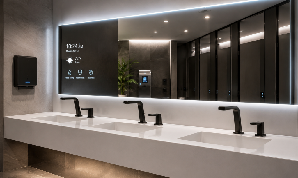
Commercial Touchless Faucet Commissioning
Commissioning verifies that the installed system performs correctly under final field conditions. Sensor faucets should be tested after surrounding finishes, basins, mirrors, lighting, power, supplies, soap systems, and user approach conditions are substantially complete.
Verify Installation
Exact model, mounting, deck conditions, connections, supply, power, accessories, service access.
Verify User Interaction
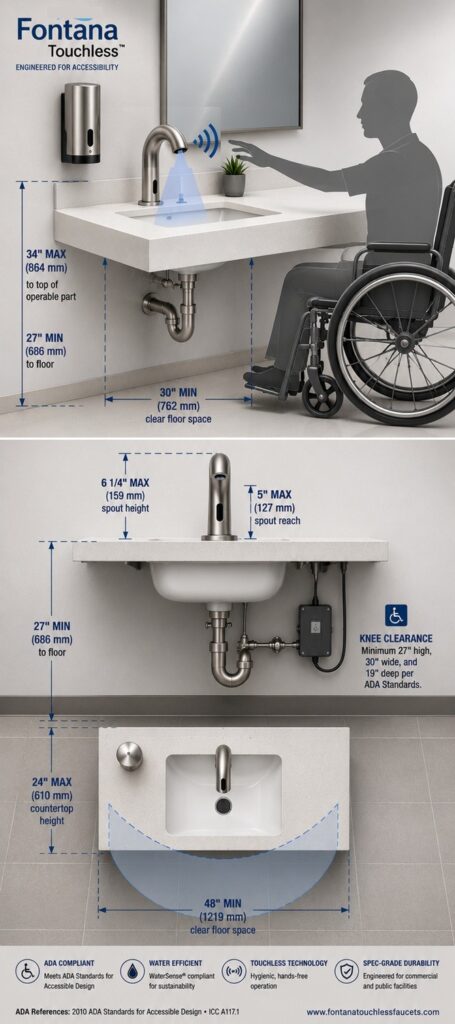
Hand detection, shutoff, comfortable reach, stream landing, soap activation, accessible use.
Stress the Environment
Check mirrors, reflections, adjacent sensors, cleaning activity, pass-by traffic, lighting, and nuisance activation.
Record the Baseline
Final settings, model, power, flow, mixing, commissioning date, responsible party, O&M references.
| Commissioning Test | Verify | Failure Risk if Missed |
|---|---|---|
| Sensor activation | Reliable detection in intended hand-washing zone | User frustration, repeated hand movement, complaints |
| Deactivation | Predictable shutoff after hands leave | Water waste or continuous flow |
| False activation | No nuisance triggering from reflections or pass-by movement | Water waste, premature component cycling |
| Stream landing | Water reaches intended basin zone | Splash, wet counters, poor user positioning |
| Flow / pressure | Field performance matches approved configuration | Low flow, excess flow, inconsistent use |
| Temperature / mixing | Required mixing and temperature behavior | User discomfort or project nonconformance |
| Power | Battery, AC/DC, hybrid or specified architecture works | Intermittent operation and avoidable downtime |
| Soap | Detection, dose, basin relationship, refill function | Drips, missed hands, wasted soap, dirty counters |
| Service access | Technician can reach controls, valves, filters, batteries | Excessive labor and destructive access later |


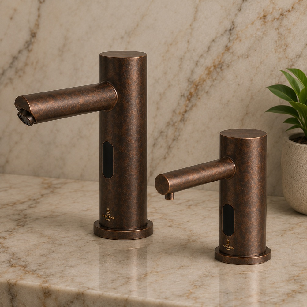



Preventive Maintenance: Maintain Performance Before It Becomes a Complaint
Preventive maintenance should be based on the exact manufacturer instructions, traffic level, water conditions, power strategy, cleaning frequency, soap formulation, operating hours, and observed failure patterns. An airport or stadium restroom should not automatically use the same service interval as a low-traffic office washroom.
| Maintenance Layer | Typical Focus | Facility Objective |
|---|---|---|
| Routine cleaning cycle | Sensor area, finish, visible leaks, soap nozzle, splash, abnormal activation | Catch obvious conditions quickly without damaging sensors or finishes |
| Periodic operational check | Activation, shutoff, flow, soap dose, power indications, valve noise | Identify performance drift before failure |
| Technical preventive service | Filters, strainers, aerators, batteries, solenoid/valve function, connections | Restore hydraulic and control performance |
| Annual / planned lifecycle review | Failure history, parts use, water use, settings, documentation, spare inventory | Decide whether repair, standardization, retrofit, or upgrade offers better value |







Sensor Maintenance & Detection Stability
A sensor complaint does not automatically mean the sensor has failed. The root cause may involve contamination, reflective surfaces, installation geometry, lighting, power, wiring, controller settings, water conditions, or the valve subsystem.
No Activation
Check water supply, power, sensor cleanliness, detection, wiring, controller, filter, valve and solenoid.
False Activation
Check reflections, adjacent fixtures, moving objects, cleaning activity, calibration and sensor field.
Intermittent Activation
Check battery/power stability, connections, sensor contamination, field conditions and pressure.
Premature Shutoff
Check hand position, basin relationship, sensor field, controller logic, reflective conditions and final settings.
Preserve the commissioning baseline
Before changing sensor settings, compare current behavior with the documented commissioning configuration. Random recalibration can turn a hydraulic or power problem into a second sensor problem.



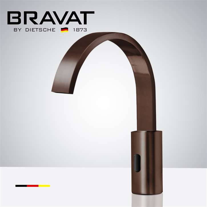
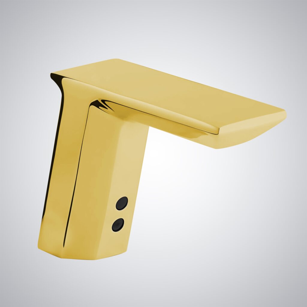

Battery, AC/DC & Hybrid Power Change the Maintenance Model
Power strategy is not merely an installation detail. It determines service intervals, spare inventory, failure behavior, electrical coordination, access requirements, and facility response procedures.
Hydraulics: Filters, Strainers, Valves, Solenoids & Flow
Low flow, delayed flow, continuous water, noise, or inconsistent shutoff should be diagnosed as a system. Do not replace the solenoid first simply because it is visible in the symptom chain.
Supply
Confirm isolation valves, available pressure, supply lines, restrictions and debris.
Filtration
Inspect strainers, filters, aerators and flow regulators for debris or mineral accumulation.
Valve
Evaluate solenoid/valve opening, closing, noise, diaphragm condition and control signal.
Outlet
Verify stream quality, aeration, flow configuration and actual landing zone inside the basin.
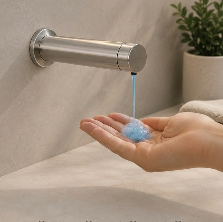

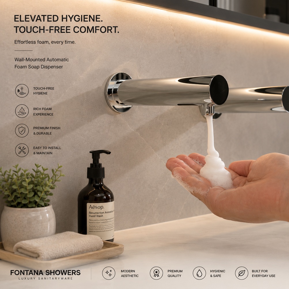
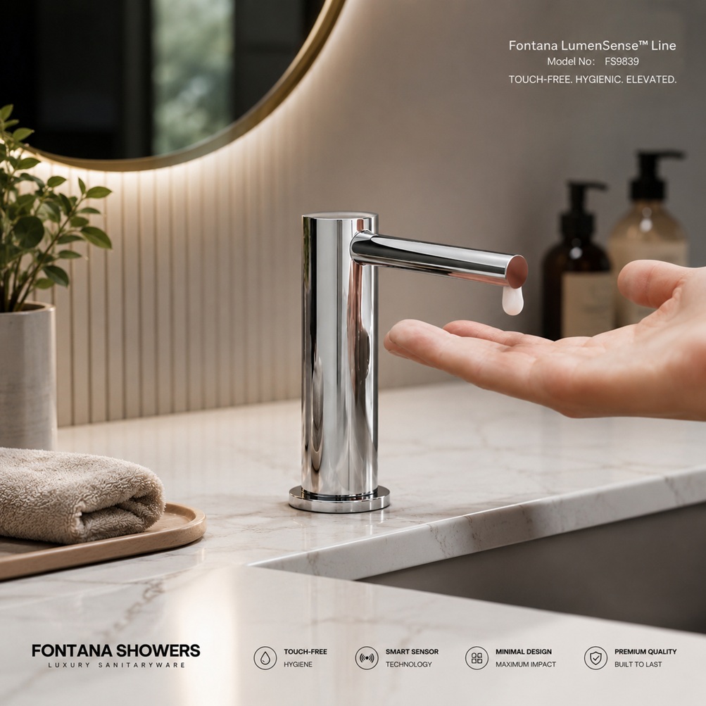
Automatic Soap Dispenser Lifecycle Engineering
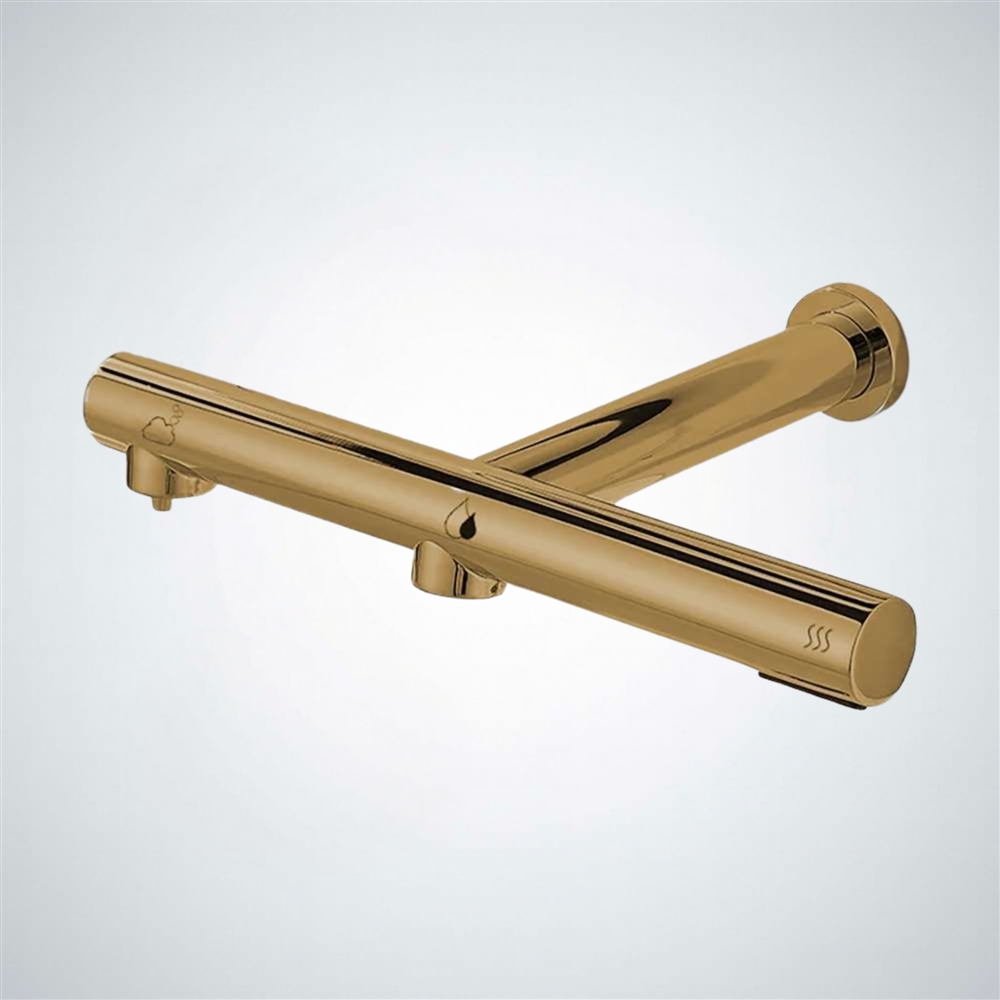
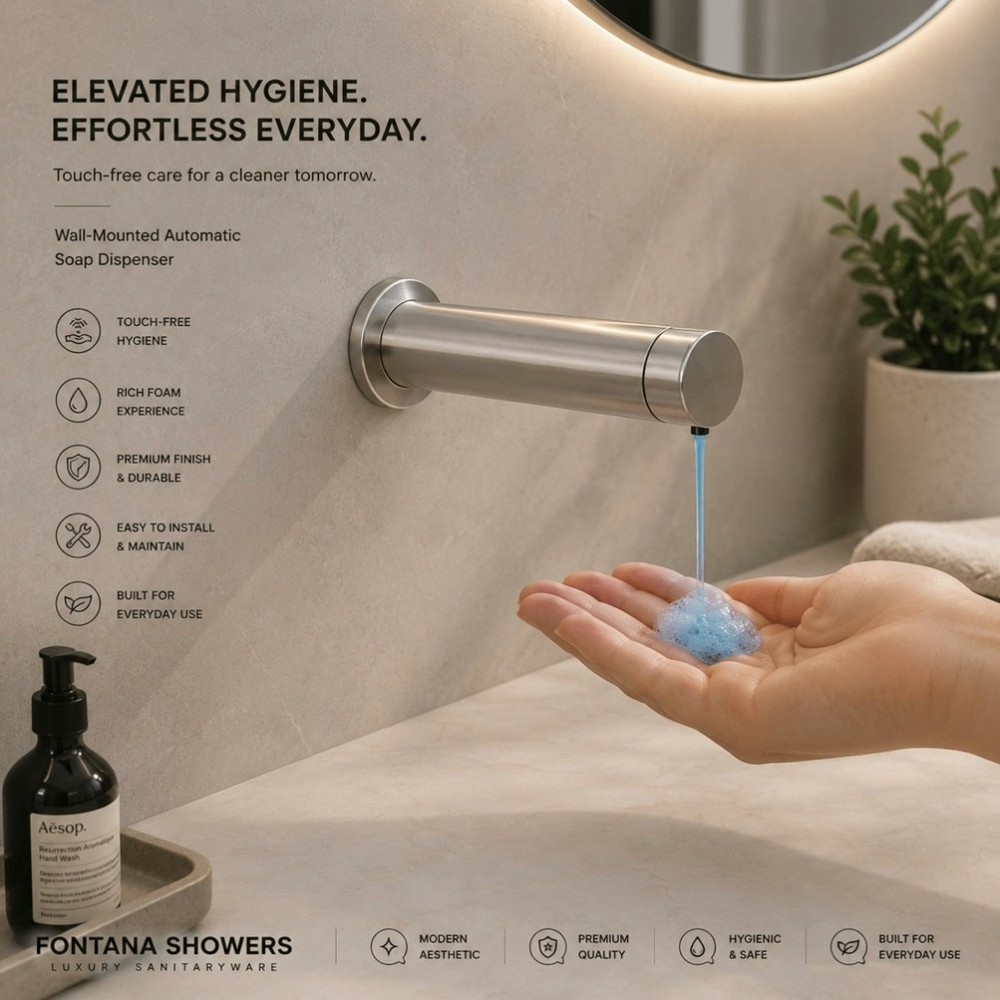
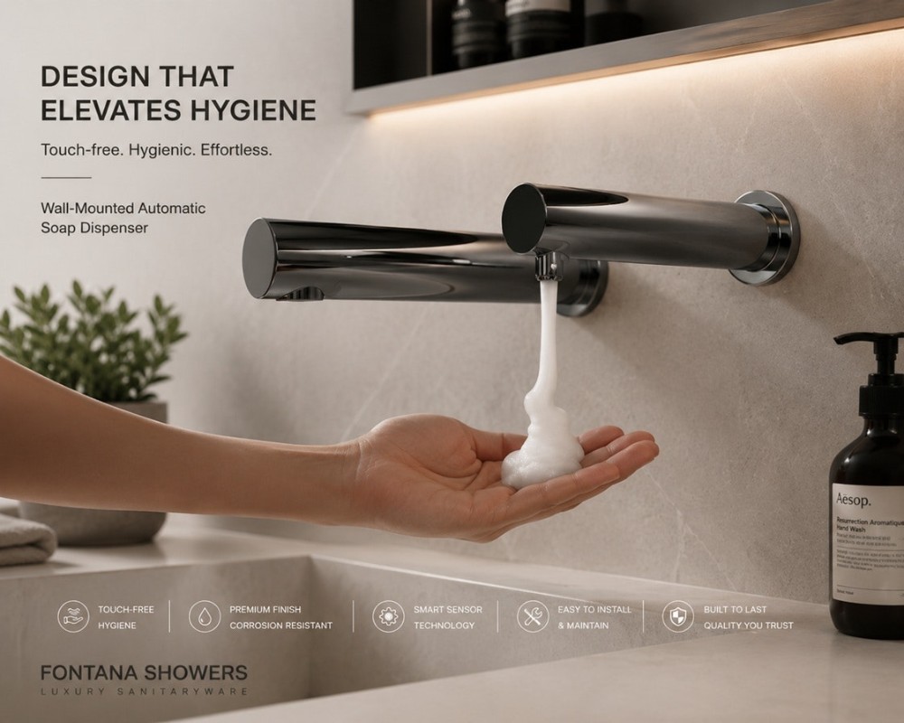
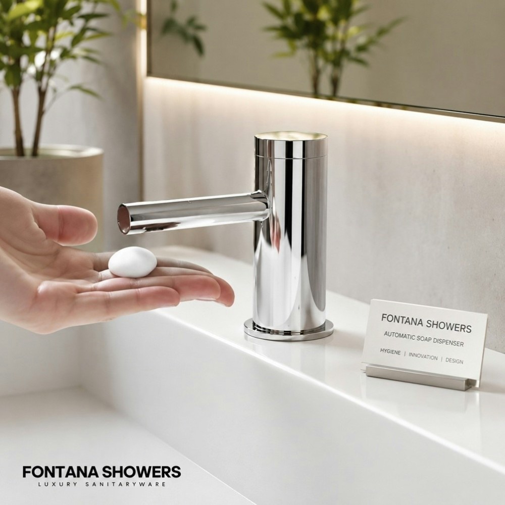
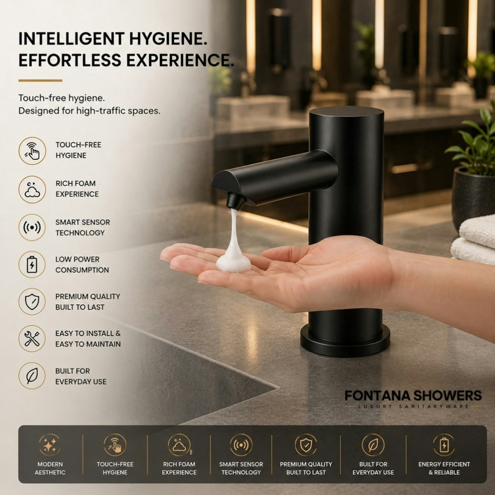
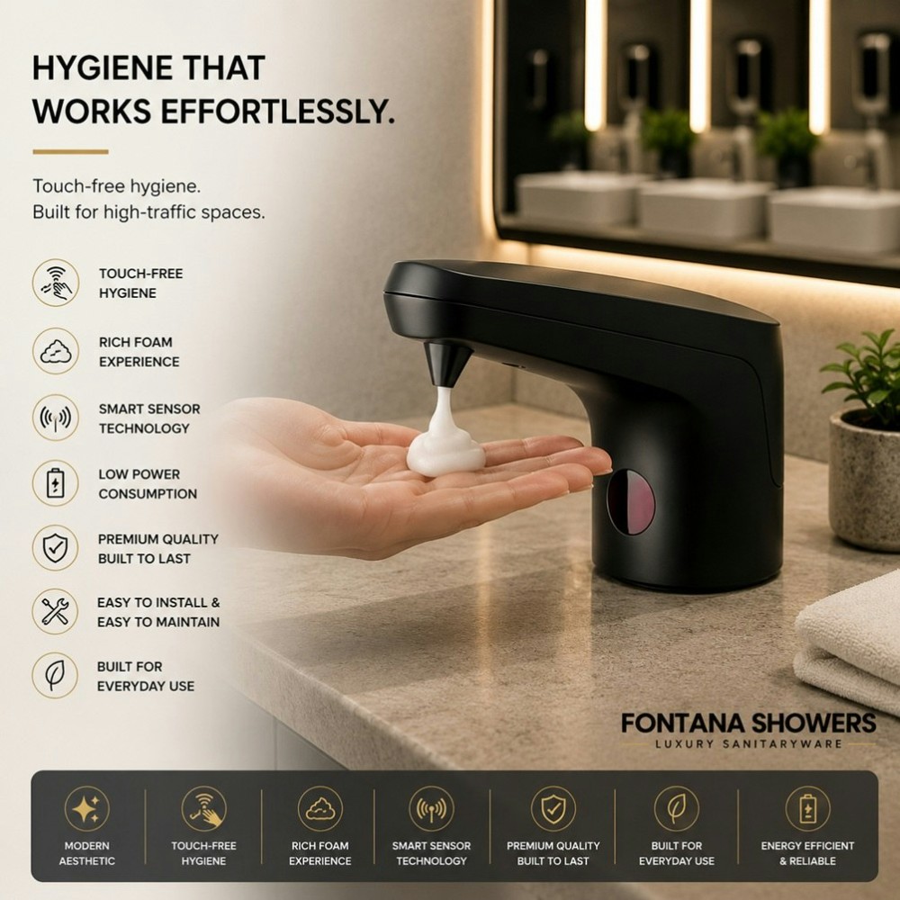
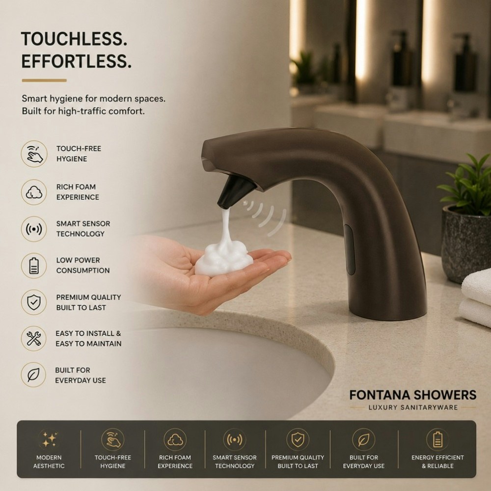
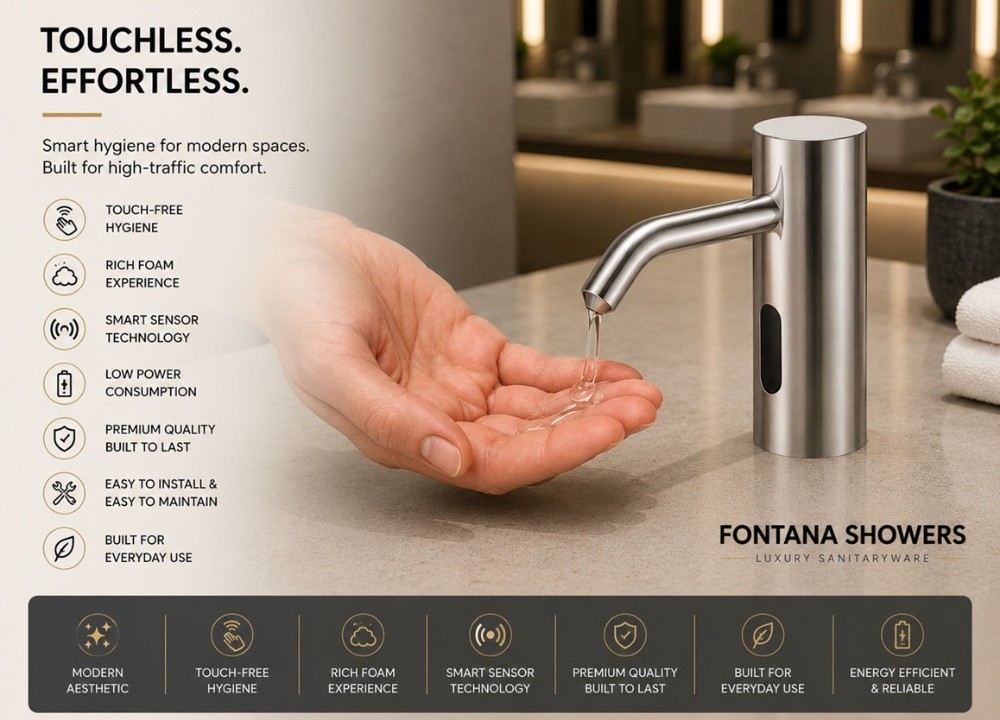
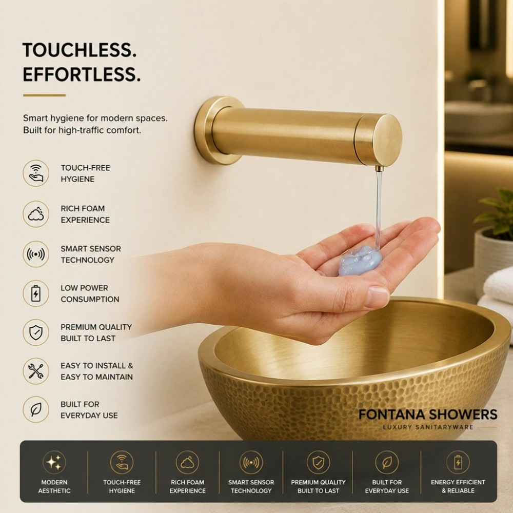
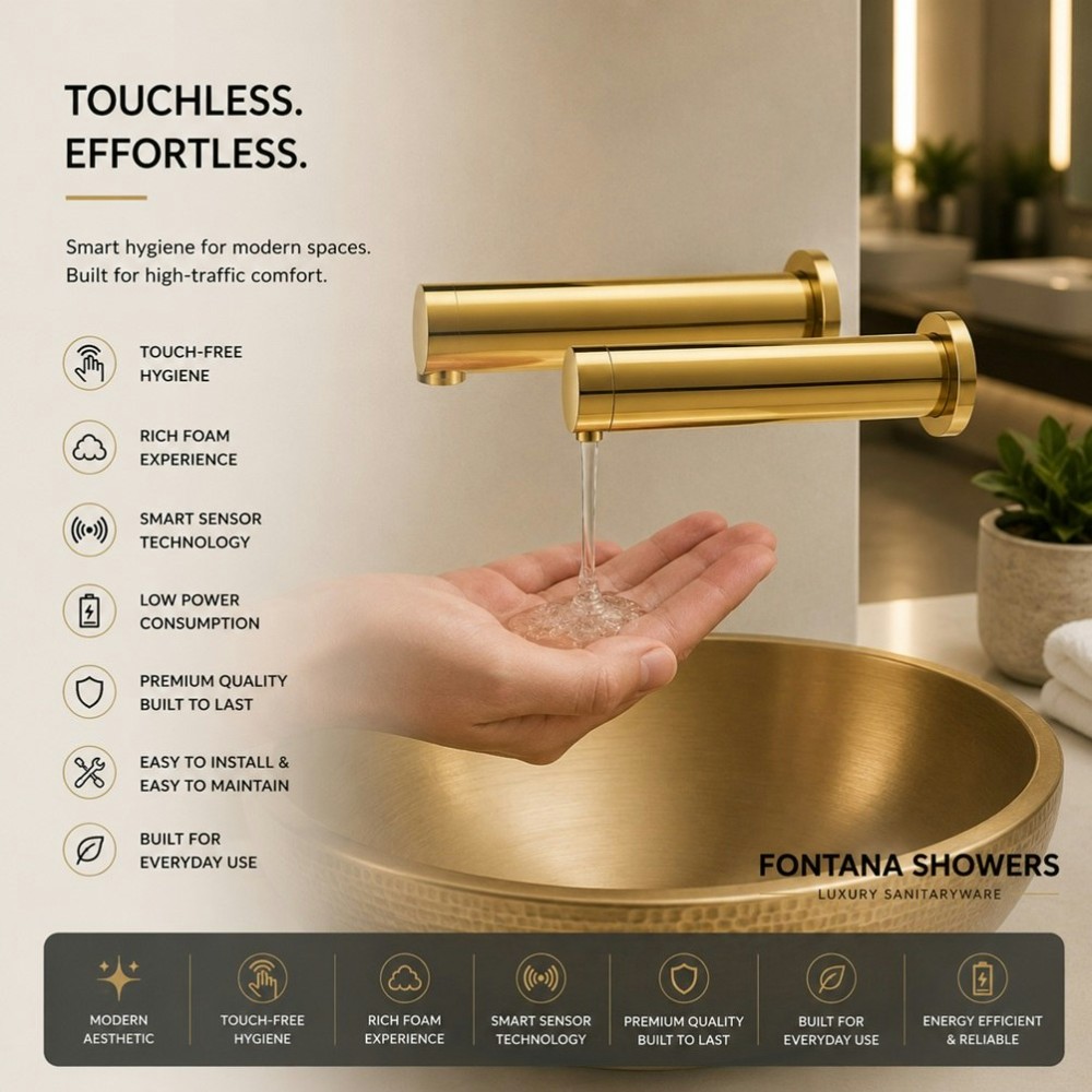
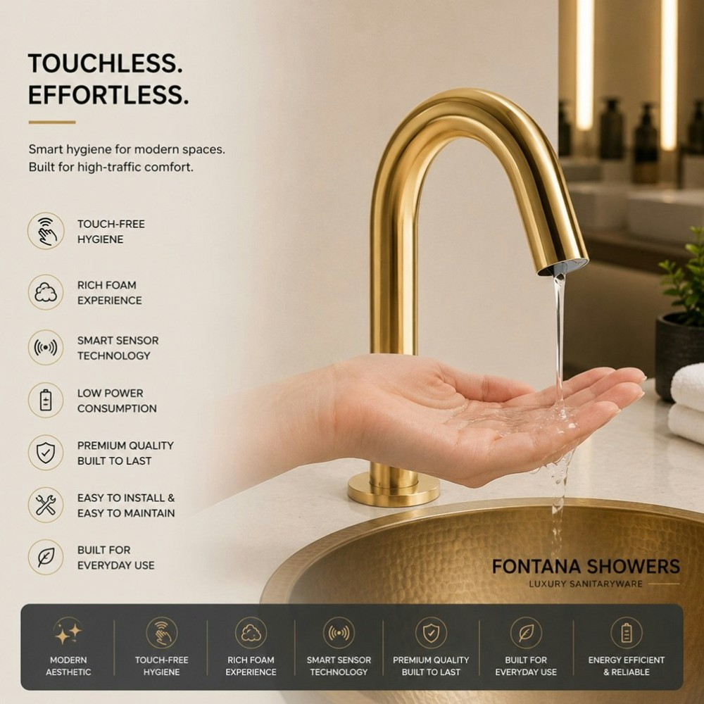
The soap dispenser is part of the handwashing system. It has its own sensing, power, fluid, pump, tubing, nozzle, refill, service-access, cleaning and asset-management requirements.
Soap Compatibility
Use the approved soap type and viscosity for the exact dispenser/pump system. Formulation changes can affect delivery and clogging.
Dosage
Verify the intended dose and consistency. Excess dose increases consumable cost and mess; insufficient dose affects user experience.
Refill Strategy
Document reservoir capacity, refill interval, access, responsible staff and centralized/MultiFeed architecture where used.
Nozzle & Tubing
Include cleaning, priming and obstruction diagnosis in the maintenance procedure.
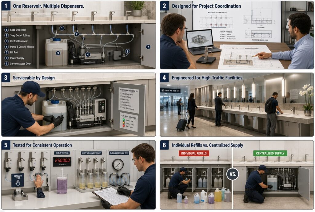
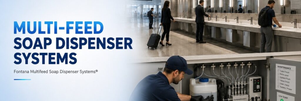
MultiFeed Systems: Centralization Changes the Maintenance Workflow
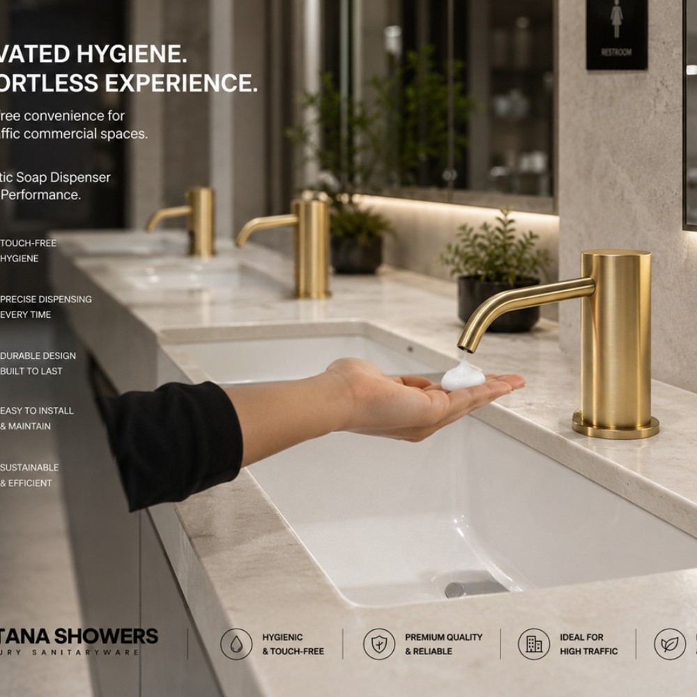
In large multi-station restrooms, centralized soap architectures can reduce repetitive under-counter refill tasks when the system is properly designed. The maintenance plan should document reservoir location, approved soap, tubing topology, pump/control components, priming, cleaning, refill thresholds, isolation procedures and spare parts.
Centralization is valuable when it reduces service burden without creating a single inaccessible failure point.


Commercial Touchless Faucet Troubleshooting Matrix
Structured diagnosis is faster and less expensive than random part replacement. Start with the simplest upstream causes before replacing control components.
| Symptom | First Checks | Then Evaluate |
|---|---|---|
| No activation | Supply, power, battery, sensor cleanliness, obvious obstruction | Wiring, controller, filter, solenoid/valve, pressure |
| Continuous flow | Sensor obstruction, reflections, calibration, debris | Valve/solenoid, controller signal, diaphragm or internal condition |
| Low flow | Supply stop, pressure, aerator, filter/strainer | Flow regulator, valve restriction, supply line, mineral buildup |
| Intermittent operation | Battery/power, connections, sensor surface | Reflections, controller, pressure variation, valve behavior |
| Excessive splash | Spout reach, stream landing, flow, basin geometry | Faucet setback, aeration, user position, basin depth/shape |
| Soap misses hands | Dispenser position, sensor field, dose, nozzle | Basin relationship, user approach, mounting and calibration |
| Soap not dispensing | Reservoir, soap compatibility, power, nozzle | Pump, tubing, priming, controller, blockage |
Create a Digital Touchless Fixture Asset Registry
Large facilities should not depend on institutional memory. Every installed fixture family should have a searchable digital record connecting location, exact product, commissioning data, O&M documents, BIM, service events, spare parts and replacement history.
| Asset Field | Recommended Record | Lifecycle Value |
|---|---|---|
| Location | Building, floor, restroom, lavatory position | Technician can identify the exact asset quickly |
| Product identity | Manufacturer, descriptive name, exact model/SKU, finish | Prevents wrong replacement parts or assumptions |
| Configuration | Flow, power, mixing, sensor/control type, soap architecture | Supports accurate diagnosis |
| Commissioning | Date, final settings, test results, responsible party | Creates performance baseline |
| Documentation | Spec sheet, installation manual, O&M, BIM/CAD, warranty | Reduces search time during service |
| Service history | Date, symptom, diagnosis, part, labor, downtime | Reveals recurring patterns |
| Replacement planning | Critical spares, lead time, approved alternates, lifecycle status | Supports procurement and capital planning |
Do Not Let BIM Die at Construction Turnover
Where the owner’s asset-management platform permits it, the fixture record should connect design and operations: BIM object → exact product data → installation instructions → commissioning record → maintenance manual → replacement parts → service history.
The result is a more useful digital asset than a geometry-only object used once during design coordination.
Traffic-Based Maintenance Strategy
Calendar intervals alone can be misleading. Facilities should combine manufacturer requirements with actual traffic, activation demand, water quality, cleaning frequency and observed failure data.
Moderate Traffic
Controlled-access offices and lower-use commercial spaces can emphasize periodic functional inspection and documentation.
High Traffic
Universities, retail, hospitality public areas and office towers benefit from standardized fixtures, preventive checks and accessible spares.
Extreme Traffic
Airports, stadiums, arenas and transit hubs should prioritize rapid diagnostics, spare inventory, accessible controls, centralized records and repeatable maintenance procedures.
Standardization Across Large Facilities
Reducing unnecessary product variation can be one of the highest-value lifecycle decisions for a large owner. Standardization simplifies technician training, troubleshooting, documentation, battery and part inventory, warranty administration, and replacement procurement.
One product family is not always the answer
Standardize where application requirements are genuinely similar. Healthcare, luxury hospitality, public stadium restrooms and back-of-house staff facilities may need different products. The goal is controlled variation—not forced uniformity.
Lifecycle Cost: Purchase Price Is Only the Beginning
A commercial touchless faucet should be evaluated using total cost of ownership rather than fixture price alone.
Lifecycle cost equation
Initial fixture + installation + commissioning + consumables/power + preventive maintenance + corrective labor + replacement components + downtime + water use + premature replacement = ownership cost.
What Each Project Team Should Own
Lifecycle performance improves when responsibilities are defined before turnover.
Architect
Mounting, basin relationship, accessible placement, finish, soap location, counter/millwork and service access.
MEP / Plumbing Engineer
Supply, pressure, flow, mixing, valve architecture, filtration, power coordination, shutoffs and commissioning requirements.
Contractor
Correct installation, approved submittal, model records, settings, deviations, test results, manuals and warranty turnover.
Facility Manager
Cleaning protocol, preventive service, asset registry, parts inventory, failure tracking, staff training and replacement strategy.
Facility Handover Package
Do not hand the owner a random folder of PDFs. Deliver a usable operating package.
Commercial Touchless Lifecycle FAQ
Practical answers for owners, AEC teams and facility operations.
How often should a commercial touchless faucet be maintained?
There is no universal interval. Follow the exact manufacturer’s requirements, then adjust facility preventive maintenance according to traffic, water quality, cleaning frequency, operating hours and observed performance.
Should batteries be replaced only when the faucet stops?
Not necessarily. High-traffic owners may prefer planned battery management to reduce unpredictable downtime. Use the exact product’s battery specification and service guidance.
Why does a touchless faucet activate by itself?
Possible causes include reflective surfaces, contamination, sensor field/calibration, adjacent movement, lighting conditions, electrical/control issues or valve behavior. Diagnose the system before replacing parts.
What usually causes low flow?
Potential causes include partially closed supplies, pressure changes, clogged aerators or flow controls, filters/strainers, valve contamination, mineral buildup or supply-line restrictions.
Should sensor settings be changed during every service call?
No. Compare current behavior to the commissioning baseline first. The cause may be hydraulic, power-related, environmental or mechanical rather than calibration.
Do automatic soap dispensers need a separate maintenance plan?
Yes. Soap viscosity, dosage, reservoirs, pumps, tubing, nozzles, power, sensors, refill intervals, cleaning and service access all affect performance.
Why keep BIM and digital product files after construction?
They can connect an installed asset to exact model data, location, manuals, replacement components and service history, reducing maintenance research time.
What is the purpose of commissioning?
To prove the final installed system works under actual field conditions and to create a documented performance baseline for future facility service.
Specify for Day One. Engineer for Year Ten.
The strongest commercial touchless systems are designed around predictable sensing, controlled water delivery, documented power, accessible valves and filters, coordinated basins, maintainable soap systems, identifiable spare parts, technician-ready documentation, and measurable long-term performance.
Educational and planning guidance only. Always verify the exact product’s current manufacturer documentation, project specifications, adopted codes, authority-having-jurisdiction requirements, warranty instructions, cleaning instructions and maintenance procedures.
Related Commercial Touchless Faucet Installation Guides